
Isomac Tea with Gicar NRL30 - wiring help?
-
Iso_Millenium
- Posts: 6
- Joined: 3 years ago
Hi all,
I was lucky (?) enough to pick up an Isomac Tea recently but after a few months of use it literally said "poof". A repair shop quoted an ungodly amount for replacing the control box (which they said was the issue) so instead I ordered a Gicar NRL30 9.1.40.71G which supposedly fits into the Tea .
However, I don't seem to able to find the correct wiring schematics for the NRL30 into my machine. It's also my very first repair so I feel a bit at loss now and was hoping someone can help me started here.
Thanks all,
/HK
Picture 1: Old wiring (why is it wired to itself with the red connector?)
Picture 2: Gicar NRL30 setup
-
Iso_Millenium (original poster)
- Posts: 6
- Joined: 3 years ago
-
jpboyt
- Posts: 220
- Joined: 14 years ago
Unfortunately the control you have chosen won't do what you want. You have acquired a simple auto-fill box that only runs the pump and fill solenoid. Your RL30 box uses a jumper wire from one of the AC incoming leads to the COM lug which feeds the backside of the Dual Pole single throw relay. Your original control handled the heating element also. You just can't get to there from here.
jpboyt
jpboyt
-
JRising
- Team HB
- Posts: 3736
- Joined: 5 years ago
In his first picture, the "microswitch" is clearly jumped right at the box. So other than powering the element circuit at all times and relying on the in-series p-stat to control it, the only difference would be leaving the element powered when the reservoir goes empty.
That said, if you really need to ask "Why is it wired to itself" when the diagram is clearly printed on a sticker on the side, you would be better off using the box intended for that unit, or paying a professional to do the job. This is not an insult, just an observation, I have no idea how much a shop quoted you to do the job correctly, nor if you paid them to do the diagnosis for you, but let's not insult them and then come running to the next person for more free advice, do you insult us next?
That said, if you really need to ask "Why is it wired to itself" when the diagram is clearly printed on a sticker on the side, you would be better off using the box intended for that unit, or paying a professional to do the job. This is not an insult, just an observation, I have no idea how much a shop quoted you to do the job correctly, nor if you paid them to do the diagnosis for you, but let's not insult them and then come running to the next person for more free advice, do you insult us next?
-
Iso_Millenium (original poster)
- Posts: 6
- Joined: 3 years ago
Thanks for the response!jpboyt wrote:Unfortunately the control you have chosen won't do what you want. You have acquired a simple auto-fill box that only runs the pump and fill solenoid. Your RL30 box uses a jumper wire from one of the AC incoming leads to the COM lug which feeds the backside of the Dual Pole single throw relay. Your original control handled the heating element also. You just can't get to there from here.
jpboyt
That's unfortunate, I had hoped the NRL30 would work based on the following post from a few years back: /repairs/is ... ml#p552738.
I would not have minded using a PRAL3 unit but they do not seem to be available anymore, hence my search for an alternative box.
-
Iso_Millenium (original poster)
- Posts: 6
- Joined: 3 years ago
Thanks for the response!JRising wrote:In his first picture, the "microswitch" is clearly jumped right at the box. So other than powering the element circuit at all times and relying on the in-series p-stat to control it, the only difference would be leaving the element powered when the reservoir goes empty.
That said, if you really need to ask "Why is it wired to itself" when the diagram is clearly printed on a sticker on the side, you would be better off using the box intended for that unit, or paying a professional to do the job. This is not an insult, just an observation, I have no idea how much a shop quoted you to do the job correctly, nor if you paid them to do the diagnosis for you, but let's not insult them and then come running to the next person for more free advice, do you insult us next?
Seeing that there's a sensor on the reservoir that does connect to the box and based on the following thread I figured the new box would be fine: Isomac Millennium Repair Brain-board
I would not have minded using a PRAL3 unit but they do not seem to be available anymore, hence my search for an alternative box. I paid for diagnosis but then they quoted me 400+ euros for the repair. Do not think I'm insulting them, and do not see why you'd think I'd insult people here
-
homeburrero

- Team HB
- Posts: 4894
- Joined: 13 years ago
I agree with others, that your original controller had a capability for switching off power to the element circuit (resistencia) based on boiler or reservoir switch sensors, and the replacement does not have that.
In your case, since your Isomac Tea has a high amperage microswitch that cuts off power to the system when the reservoir is low or empty, and doesn't use the controller to do that, then I think you could get by with this simpler controller, even though it's not a full functional replacement. That's why you sometimes see it sold as a good-enough replacement for that machine (for example, https://www.espressocare.com/products/i ... eu-version , complete with the jumper wire for the power.)
I think the schematics you shared are a little confusing, especially where they label pin 8 of the Gicar as 'resistencia' and sort of imply that it's equivalent to pin 3 of the ProElInd. It is not. Pin 8 of the Gicar is where it gets power for the relay that energizes the pump and the solenoid. That power can come from any wire that is after both the tank switch and the on/off switch, and has nothing to do with the resistencia circuit. Typically it's powered via the same wire that powers the controller transformer via a piggyback connector on pin 2. That's the idea behind the vertical dotted orange line. Pin 3 of the ProElInd, on the other hand, is where power from the controller goes out to the element circuit. This ProElInd controller has smarts to allow power to the element based on connectivity at the microswitch and the livello sensor pins. The simpler Gicar replacement does not have that capability and therefore has no 'resistencia' pin.
P.S.
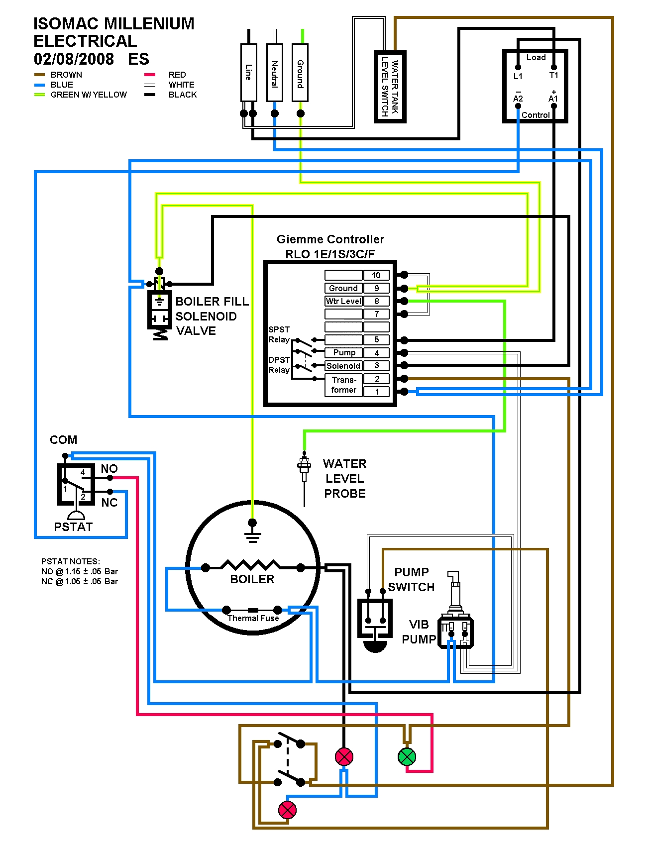
Eric Svendson has an electrical diagram for the Millennium (here) that shows how that tank switch works with the ProElInd microswitch pins jumpered. It's complicated and a little unusual, and your machine may or not be wired like the diagram. Before making wiring changes and plugging it in be sure you enlist some electrical expertise to help you if you don't fully understand it yourself.
In your case, since your Isomac Tea has a high amperage microswitch that cuts off power to the system when the reservoir is low or empty, and doesn't use the controller to do that, then I think you could get by with this simpler controller, even though it's not a full functional replacement. That's why you sometimes see it sold as a good-enough replacement for that machine (for example, https://www.espressocare.com/products/i ... eu-version , complete with the jumper wire for the power.)
I think the schematics you shared are a little confusing, especially where they label pin 8 of the Gicar as 'resistencia' and sort of imply that it's equivalent to pin 3 of the ProElInd. It is not. Pin 8 of the Gicar is where it gets power for the relay that energizes the pump and the solenoid. That power can come from any wire that is after both the tank switch and the on/off switch, and has nothing to do with the resistencia circuit. Typically it's powered via the same wire that powers the controller transformer via a piggyback connector on pin 2. That's the idea behind the vertical dotted orange line. Pin 3 of the ProElInd, on the other hand, is where power from the controller goes out to the element circuit. This ProElInd controller has smarts to allow power to the element based on connectivity at the microswitch and the livello sensor pins. The simpler Gicar replacement does not have that capability and therefore has no 'resistencia' pin.
P.S.
Eric Svendson has an electrical diagram for the Millennium (here) that shows how that tank switch works with the ProElInd microswitch pins jumpered. It's complicated and a little unusual, and your machine may or not be wired like the diagram. Before making wiring changes and plugging it in be sure you enlist some electrical expertise to help you if you don't fully understand it yourself.
Pat
nínádiishʼnahgo gohwééh náshdlį́į́h
nínádiishʼnahgo gohwééh náshdlį́į́h
-
Iso_Millenium (original poster)
- Posts: 6
- Joined: 3 years ago
Thanks homeburrero, this is extremely helpful. I'll enlist some help on this and hope to give a positive update in the coming weeks. Thanks!homeburrero wrote:I agree with others, that your original controller had a capability for switching off power to the element circuit (resistencia) based on boiler or reservoir switch sensors, and the replacement does not have that.
In your case, since your Isomac Tea has a high amperage microswitch that cuts off power to the system when the reservoir is low or empty, and doesn't use the controller to do that, then I think you could get by with this simpler controller, even though it's not a full functional replacement. That's why you sometimes see it sold as a good-enough replacement for that machine (for example, https://www.espressocare.com/products/i ... eu-version , complete with the jumper wire for the power.)
I think the schematics you shared are a little confusing, especially where they label pin 8 of the Gicar as 'resistencia' and sort of imply that it's equivalent to pin 3 of the ProElInd. It is not. Pin 8 of the Gicar is where it gets power for the relay that energizes the pump and the solenoid. That power can come from any wire that is after both the tank switch and the on/off switch, and has nothing to do with the resistencia circuit. Typically it's powered via the same wire that powers the controller transformer via a piggyback connector on pin 2. That's the idea behind the vertical dotted orange line. Pin 3 of the ProElInd, on the other hand, is where power from the controller goes out to the element circuit. This ProElInd controller has smarts to allow power to the element based on connectivity at the microswitch and the livello sensor pins. The simpler Gicar replacement does not have that capability and therefore has no 'resistencia' pin.
P.S.
Eric Svendson has an electrical diagram for the Millennium (here) that shows how that tank switch works with the ProElInd microswitch pins jumpered. It's complicated and a little unusual, and your machine may or not be wired like the diagram. Before making wiring changes and plugging it in be sure you enlist some electrical expertise to help you if you don't fully understand it yourself.
-
Logger
- Posts: 1
- Joined: 3 years ago
Hi All. First post newby here. Stumbled across this thread when replacing the controller board in my Isomac Millennium today. I have owned it for almost twenty years and it is like the proverbial axe. 5 new heads and 5 new handles. This is the third time I have replaced the controller. Previously it had the PRAL3 controller fitted. I was initially surprised when the Gicar NRL30 unit arrived in the mail as I specifically ordered a PRAL3. Then I remembered the PRAL is no longer available.
So I came here looking for the wiring swap schema. For anyone else who has an early model Tea or Millennium I can confirm the third diagram above, posted by Iso_Millenium, showing the wiring transpositions works fine.
I did notice there is an error in the second image titled "GICAR NRL30/1E-2C/F". The left hand side showing blue & brown wires on the Main Supply L1 L2, has the wires transposed and connected to the wrong terminals.
It should be Blue L1 and Brown L2 to match the main diagram. Was obviously a typo by whoever made the diagram & I would hate someone to connect it that way by mistake.
Now that my Millennium is back up an running I do have a question. When a Tea or Millennium is in good health how often should the element be cycling on? Is twice a minute for 5 seconds too often? I cannot see any obvious leaks, but the pressure needle drops at a rate that its movement is just noticeable, triggering the pressurestat & element every 30 sec or so. I cannot recall if that is normal.
Thanks for the great resource of information BTW.
-
Iso_Millenium (original poster)
- Posts: 6
- Joined: 3 years ago
Hi all,
It took a while to get sorted but I have jumped the cables as described in the 3rd picture I posted. Machine turned on nicely and is brewing coffee again.
Thanks for all the help.
It took a while to get sorted but I have jumped the cables as described in the 3rd picture I posted. Machine turned on nicely and is brewing coffee again.
Thanks for all the help.
