
La Pavoni Professional - Weird Wiring?
-
shrugrice
- Posts: 17
- Joined: 1 year ago
I just purchased a vintage La Pavoni. I think it is the 1980-83 model, based on a number of things but especially the similarity to the wiring and component configuration photograph for those years shown on this page: http://www.francescoceccarelli.eu/lapav ... mi_eng.htm.
When I received the unit it did not heat up. I eventually determined that the pressurestat had no current running across it, so I replaced that and it works.
However, I'm a little confused by the state of the wiring, even though the thing works. So I'm trying to make sure I understand, both out of curiosity and to make sure there isn't some problem with the current wiring that could lead to a problem later on.
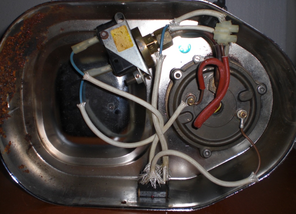
Here's a photo of the overall wiring with the new pressurestat:
Note that there are three wires going into the switch, not four, which you can also see here:
This is what gives me pause a bit. While the photo listed on the page mentioned above looks like it might be setup in a similar way, there is a diagram that circulates on this site showing "La Pavoni Professional Wiring" ([url]/repairs/la ... 23577.html) that shows four wires going into the switch, two directly from the chord, and then forming a circuit going through the pressurestat and heating element.
In mine, there is a wire coming in from the chord that goes directly to the switch (on the top side of the switch closer to the camera). Then from there there is a wire going into the pressurestat, then another from the pressurestat into the heating element on the bottom contact, where it then proceeds across to the other contact presumably, and then things get a little strange.
From the contact on the top of the heating element there are two wires, one goes into the switch on the "on" side where it seems to terminate (maybe this drives the light for the switch?). The other wire (the red one) is the one that seems to complete the circuit. It goes into the cavity of where the thermofuse is I think and then proceeds to the chord.
Now I'm sure it's clear I have a rudimentary at best explanation of the electrical wiring, but I'm trying. Is there anyone that can explain what's going on here? Is this a standard wiring for some models, or is it unusual? I'd be happy to provide any other photo angles if necessary.
Very curious to hear thoughts.
When I received the unit it did not heat up. I eventually determined that the pressurestat had no current running across it, so I replaced that and it works.
However, I'm a little confused by the state of the wiring, even though the thing works. So I'm trying to make sure I understand, both out of curiosity and to make sure there isn't some problem with the current wiring that could lead to a problem later on.
Here's a photo of the overall wiring with the new pressurestat:
Note that there are three wires going into the switch, not four, which you can also see here:
This is what gives me pause a bit. While the photo listed on the page mentioned above looks like it might be setup in a similar way, there is a diagram that circulates on this site showing "La Pavoni Professional Wiring" ([url]/repairs/la ... 23577.html) that shows four wires going into the switch, two directly from the chord, and then forming a circuit going through the pressurestat and heating element.
In mine, there is a wire coming in from the chord that goes directly to the switch (on the top side of the switch closer to the camera). Then from there there is a wire going into the pressurestat, then another from the pressurestat into the heating element on the bottom contact, where it then proceeds across to the other contact presumably, and then things get a little strange.
From the contact on the top of the heating element there are two wires, one goes into the switch on the "on" side where it seems to terminate (maybe this drives the light for the switch?). The other wire (the red one) is the one that seems to complete the circuit. It goes into the cavity of where the thermofuse is I think and then proceeds to the chord.
Now I'm sure it's clear I have a rudimentary at best explanation of the electrical wiring, but I'm trying. Is there anyone that can explain what's going on here? Is this a standard wiring for some models, or is it unusual? I'd be happy to provide any other photo angles if necessary.
Very curious to hear thoughts.
-
homeburrero

- Team HB
- Posts: 4894
- Joined: 13 years ago
I think your wiring scheme was used in some pre-1984 models. This wiring simply doesn't make use of the other pole of the double pole switch but should work, including the switch light. It would be arguably better to wire both the line and the neutral wire through that DPST switch, per this wiring diagram, but not necessary, especially if you know that on your machine it's the 'hot' wire from the plug that does go straight to the on/off switch. For you to rewire it per the diagram you would need to crimp in a female faston connector and connect the wire in that red thermofuse switch to the unused pin of the switch rather than running it directly to the element.shrugrice wrote:Now I'm sure it's clear I have a rudimentary at best explanation of the electrical wiring, but I'm trying. Is there anyone that can explain what's going on here? Is this a standard wiring for some models, or is it unusual?
Here's a pic from the Francesco Ceccarelli site showing a machine like yours that has only 3 rather than four wires connected to the switch:
http://www.francescoceccarelli.eu/La_Pa ... r/pr80.JPG
Pat
nínádiishʼnahgo gohwééh náshdlį́į́h
nínádiishʼnahgo gohwééh náshdlį́į́h
-
shrugrice (original poster)
- Posts: 17
- Joined: 1 year ago
Thank you, Pat. Glad to know it is not wrong. I think the part I found off was the wiring terminating in the on side of that switch. Now I am wondering if the light will not work of that wire were removed. Otherwise, it seems unnecessary.
-
homeburrero
- Team HB
- Posts: 4894
- Joined: 13 years ago
That's exactly right. With this scheme the only purpose of that wire is to complete the circuit to the switch light.shrugrice wrote:I think the part I found off was the wiring terminating in the on side of that switch. Now I am wondering if the light will not work of that wire were removed. Otherwise, it seems unnecessary.
Pat
nínádiishʼnahgo gohwééh náshdlį́į́h
nínádiishʼnahgo gohwééh náshdlį́į́h
