
Project: PID NS Oscar: Result: Modded now Graphing/Learning
-
ciordia9
- Posts: 32
- Joined: 18 years ago
I've got two projects I'm working through. The first one is the modding of my Oscar to be tighter, the other thinking of making the Eureka (NS) MDE grinder doserless.
Nuova Simonelli Oscar:

I picked this little one up about a year and a half ago ±. It's been a trooper but I desire to learn more and understand this machine and others. The entire universe of coffee has been a fantastic voyage and this seems like an appropriate way of continuing my education. Know that I am a novice when it comes to these insides. I do not profess to have anything but a good sense of curiosity, looking for good questions and good answers to apply.
From my reading and exploring over the past few months I've found a wealth of thoughts but where they fall in difficulty, ability, and time I'm not sure, thats why I'm here. Help me sort the signal out.
Modifications possibilities:
Not everything is necessary; I just wanted to think without being boxed in. I think this is everything I could really do to the machine. I think some things stack. If I were to be cutting copper for a vacuum breaker then it doesn't seem so far an idea to tie in some gauges. Course I've never cut copper so if that has a large learning curve then both of those seem of vague relevance.
In the next week I'll have most of my tools at the ready. Scace, Omega therm, probes, PF gauge
Ebay has not too bad a price on the Fuji PXR3, but I don't know the extent or method for what I would require to do this fully.
Steam wand/Vacuum Breaker

At first I thought this was a definite. I've always run the unit 24x7, but I read on how people timer theirs and that sounded pretty nifty. Then I saw a number of techs writing that said that stresses the machine, seals, and wears the valve out which made me ponder the real need for such a device. I'm easily compelled but adding a breaker now doesn't sit as high as it did a few weeks ago.
Pressure Limiting Valve

I've yet to find this bit, can someone help point it out and how to modify it? I've got the classic NS Oscar that when it's got a blind in it still doesn't release the pressure.
Pressurestat


Clockwise more pressure, counter less? Once my gauge comes in I should be able to tune this right?
Temperature & PID Adjustments


Now my hunting for information really drops down. Gauges don't give me better shots but it might act as an easier way of catching deteriorating equipment sooner than later.
Any help, tips, resources, or ideas/things I'm forgetting are always appreciated.
-a
Nuova Simonelli Oscar:
I picked this little one up about a year and a half ago ±. It's been a trooper but I desire to learn more and understand this machine and others. The entire universe of coffee has been a fantastic voyage and this seems like an appropriate way of continuing my education. Know that I am a novice when it comes to these insides. I do not profess to have anything but a good sense of curiosity, looking for good questions and good answers to apply.
From my reading and exploring over the past few months I've found a wealth of thoughts but where they fall in difficulty, ability, and time I'm not sure, thats why I'm here.
Modifications possibilities:
- Addition of a Vacuum Breaker
Addition of Steam & Pump Gauges
General Temperature Adjustments
Advanced Adjustments via PID installation
OPV Setting
Pressure Limiting Valve Adjustments
Not everything is necessary; I just wanted to think without being boxed in. I think this is everything I could really do to the machine. I think some things stack. If I were to be cutting copper for a vacuum breaker then it doesn't seem so far an idea to tie in some gauges. Course I've never cut copper so if that has a large learning curve then both of those seem of vague relevance.
In the next week I'll have most of my tools at the ready. Scace, Omega therm, probes, PF gauge
Ebay has not too bad a price on the Fuji PXR3, but I don't know the extent or method for what I would require to do this fully.
Steam wand/Vacuum Breaker
At first I thought this was a definite. I've always run the unit 24x7, but I read on how people timer theirs and that sounded pretty nifty. Then I saw a number of techs writing that said that stresses the machine, seals, and wears the valve out which made me ponder the real need for such a device. I'm easily compelled but adding a breaker now doesn't sit as high as it did a few weeks ago.
Pressure Limiting Valve
I've yet to find this bit, can someone help point it out and how to modify it? I've got the classic NS Oscar that when it's got a blind in it still doesn't release the pressure.
Pressurestat
Clockwise more pressure, counter less? Once my gauge comes in I should be able to tune this right?
Temperature & PID Adjustments
Now my hunting for information really drops down.
- How do I adjust the pstat?
From where do I draw my best measurement?
How do I rig a PID into this?
Any help, tips, resources, or ideas/things I'm forgetting are always appreciated.
-a
-
ciordia9 (original poster)
- Posts: 32
- Joined: 18 years ago
for tweaks, anyone added some tiger paw or some form of sound/vibration damping to these units? When that pump kicks on it can put out some noise. Wonder if it can't be mitigated somehow.
-
HB

- Admin
- Posts: 22021
- Joined: 19 years ago
Sorry about not responding earlier. Lots of questions in one post intimidates me...
On the other hand, the pressurestat will wear out faster too if the machine is run 24/7. Components degraded by heat will also suffer (e.g., grouphead gaskets). Metals will be happier. Bottom line is that some components benefit from the constant temperature, some suffer from the additional exposure to heat, and others just plain wear out faster.ciordia9 wrote:Then I saw a number of techs writing that said that stresses the machine, seals, and wears the valve out which made me ponder the real need for such a device.
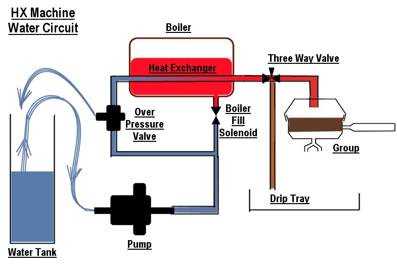
You should have a second return line to the tank. Some machines like the Wega have a return loop to a tee in the inlet line. Either way, a little poking around with this diagram from another thread should get you started:ciordia9 wrote:I've yet to find this bit, can someone help point it out and how to modify it? I've got the classic NS Oscar that when it's got a blind in it still doesn't release the pressure.
HB wrote:Jim Schulman's Adjusting vibe pump pressure on HX machines explains the mechanics, including the diagram below:
(reproduced with permission)
You should be measuring the water exiting the over-pressure valve, which you've clearly identified. The tubing at the end of the OPV may twist when you adjust, but it's easy to remove, untwist, and replace.
Yes * 2. The Sirai's adjustment isn't touchy, unlike the smaller MATER / CEME pressurestats.ciordia9 wrote:Clockwise more pressure, counter less? Once my gauge comes in I should be able to tune this right?
Ken Fox is the leading HX PID man; see threads like Should I PID my Heat Exchanger? I wonder if the great results he reports will apply to machines with lighter groups like yours. My gut reaction is "no".ciordia9 wrote:How do I rig a PID into this?
That's pretty much it, except you need some dampening agent to get a steady reading. Either a wet gauge, or snubber / coil of thin copper tubing leading to the gauge will work.ciordia9 wrote:I have no concept of its difficulty just that it'd be tied into an intersection of pipe and need to be either brought outside the machine or cut the plastic and mount them in the wall.
I moved the pump outside the case into the cabinet below. That eliminated the problem at the source - reverberation of the casing.ciordia9 wrote:for tweaks, anyone added some tiger paw or some form of sound/vibration damping to these units?
Dan Kehn
-
ciordia9 (original poster)
- Posts: 32
- Joined: 18 years ago
Thanks Dan for the response, and my belated to your belated response hehe.
I've been busy, but then held up in parts acquisition for a while now. Some of these guys are hard to come by. I went ahead and learned what I could from the Pstat side of things. If I were one to sit on a temp forever I'd be happy where it is. I now have to flush at least once to get the temp I aimed for but it's on. Reducing the brew pressure was helpful as well. I now discharge a lot more water but it's improved shot tastes quite a bit.
I've been slowly moving towards the PID. Dan you say if you wonder if I'll get as good a result, is there a reason I wouldn't? In sizings I thought the Cimbali that DK works on and the Oscar were similar in size. The only reason I really wanna go PID is due to SO's & not wanting to recalibrate that pstat every time I want to experiment.
Still need to pick up a dremel so I can hack my project box in to form. Picked up the Auber PID & SSR. Ordered a 3" probe from Omega and want to turn the stock oscar T on it's side, add another T for the vac breaker & keep the OPV. Where I'm hitting a new wall is pulling these bits apart.

How to unhook these guys without ripping things apart...
First things first, counter-clockwise for removal?
If I tweak the white, then the blue (pstat) shifts & torque is added to the boiler.
If I tweak the white and counter with the red then the pstat shifts (blue).
If I tweak the red the boiler wants to move, no counterpoint evident?
What's the cleanest way for me to remove this assembly? I feel like I'm going to rip it out with the amount of force I have at my disposal and I'd much rather not damage the equipment beyond reversibility. I always like to be able to work backwards in case of an eventuality.
I've been busy, but then held up in parts acquisition for a while now. Some of these guys are hard to come by. I went ahead and learned what I could from the Pstat side of things. If I were one to sit on a temp forever I'd be happy where it is. I now have to flush at least once to get the temp I aimed for but it's on. Reducing the brew pressure was helpful as well. I now discharge a lot more water but it's improved shot tastes quite a bit.
I've been slowly moving towards the PID. Dan you say if you wonder if I'll get as good a result, is there a reason I wouldn't? In sizings I thought the Cimbali that DK works on and the Oscar were similar in size. The only reason I really wanna go PID is due to SO's & not wanting to recalibrate that pstat every time I want to experiment.
Still need to pick up a dremel so I can hack my project box in to form. Picked up the Auber PID & SSR. Ordered a 3" probe from Omega and want to turn the stock oscar T on it's side, add another T for the vac breaker & keep the OPV. Where I'm hitting a new wall is pulling these bits apart.
How to unhook these guys without ripping things apart...
First things first, counter-clockwise for removal?
If I tweak the white, then the blue (pstat) shifts & torque is added to the boiler.
If I tweak the white and counter with the red then the pstat shifts (blue).
If I tweak the red the boiler wants to move, no counterpoint evident?
What's the cleanest way for me to remove this assembly? I feel like I'm going to rip it out with the amount of force I have at my disposal and I'd much rather not damage the equipment beyond reversibility. I always like to be able to work backwards in case of an eventuality.
-
barry

- Posts: 637
- Joined: 19 years ago
the silver nut at the pstat simply holds the pstat to the mounting bracket. to loosen the brass nut where the pipe fits to the pstat, you're going to have to hold on to the pstat to counter the torque (or really really tighten down that silver nut against the bracket).
as for the other end of the pipe, you're just going to have to torque against the boiler. if you think the nut is stuck on there, then i'd suggest hitting the nut with a torch to get it hot. often these fittings are assembled at the factory with a threadlocker, so initial disassembly can be somewhat nervewracking when it comes to pulling things off the boiler.
as for the other end of the pipe, you're just going to have to torque against the boiler. if you think the nut is stuck on there, then i'd suggest hitting the nut with a torch to get it hot. often these fittings are assembled at the factory with a threadlocker, so initial disassembly can be somewhat nervewracking when it comes to pulling things off the boiler.

-
HB
- Admin
- Posts: 22021
- Joined: 19 years ago
I friend of mine is seriously into cabinet making and woodworking. In situations like yours, he advises using iron pipes and clamps to create a crossbar and then fix the plumbing pieces you wish to secure to them. Of course it helps that he has a workshop that would make Norm Abram proud.ciordia9 wrote:What's the cleanest way for me to remove this assembly? I feel like I'm going to rip it out with the amount of force I have at my disposal and I'd much rather not damage the equipment beyond reversibility.
Dan Kehn
-
ciordia9 (original poster)
- Posts: 32
- Joined: 18 years ago
Ah, I wish I could be so lucky. I am not that tool laden, I'm a wannabe woodworker and Honey-do generalistHB wrote:Of course it helps that he has a workshop that would make Norm Abram proud.
So I got the pstat off with not as much trouble as I had thought. With that nice step in my stride I went on to trying to get the entire T off and that.. well that's back to a pita and I want to be told nice things haha.. I first thought I'd clean up the area and remove the other compression fitting to the now defunct copper piece and when I was doing that I could see the T ever so slowly bending (in or within) the boiler. That made my stomach drop so lightly retorqued it into position and tried to get the T to unscrew. Man I never knew how soft copper was. Unfortunately I can't brace the boiler and I feel like I'll either end up stripping it, destroying the port all together, or torquing the boiler's mount beyond acceptability. I'm skurrr'd as they'd say down the road.
It looks like some form of gunk might have been applied where the screw meets the boiler.. Can anyone else comment on that discoloration around that area?
I've tried a little heat in the area and that didn't get me any distance (thought I'm not sure how much heat to apply in these situations).

Any more thoughts are appreciated.
-a
-
HB
- Admin
- Posts: 22021
- Joined: 19 years ago
Sorry, I've forgotten what the goal was. I don't like the look of your project's current trajectory. Rather than fuss with the T pictured above, if the goal is to tap into the steam line, why not cut the copper tubing and splice in a tee? No risk of torquing a fitting off the boiler.ciordia9 wrote:Unfortunately I can't brace the boiler and I feel like I'll either end up stripping it, destroying the port all together, or torquing the boiler's mount beyond acceptability.
Dan Kehn
-
ciordia9 (original poster)
- Posts: 32
- Joined: 18 years ago
Trying to get a thermo probe installed.. I've been told a few different things.
1. Greg Lepore advised me to add an additional T and just take the steam's temp and that was "good enough" for calibrating the pid. Which twomartini's told me that it wasn't such a good thought at a cupping.
1.1. I attempted to go down this a bit but I've got an auber probe which is 5/32 and doesn't fit any compression I have and its short.. Probably good for steam but not good for distance and I have no real way to fit it.
2. Jack Denver said to turn my T on it's side and drop a probe down that way so I can get to the actual boiler water.
At this point I just want to turn the T on it's side, put the probe down into the tank, then with the showing male thread attach an all female T (which I'm still trying to source) and add the vacbreak and opv. I've got an omega 4" K probe which fits the compression fitting but I can't crack this T off easily.
It's funny how relatively easy this all sounded on paper and reading online but it's been a rather detailed and long project thus far. I guess everyone who gets nitty gritty has more kungfu belt levels than I originally thought was needed or this is just a murphy teaching me more lessons.
My wife asked me as I strained today whether or not we were about to invest in a new machine. :-/ heheh.
So I dunno.. I feel like if I can get the equipment unhooked, I've got just about everything to go forward. I never thought taking the bits off was going to be harder than building the new setup.
-a
